ED1-2
Estimation of Critical Current of HTS RF-SQUID
Dec.1 15:45-16:00 (Tokyo Time)
Toyohashi University of Technology, Toyohashi, Japan1
High temperature RF-SQUID consists of a superconducting loop, which has one Josephson Junction (JJ). For the operation of the RF-SQUID there is a restriction that the inductance parameter βL=2πICLS/Φ0 is in the range of 1~3, where IC is the critical current of JJ, Ls is the SQUID inductance and Φ0 is the flux quantum. However, since the both ends of the JJ of RF-SQUID are shorted by a superconducting loop, it is necessary to cut the loop to evaluate the IC. Therefore, we proposed a method to nondestructively measure the IC of the RF-SQUID using another SQUID magnetometer [1].
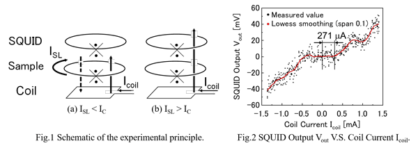
Fig.1 shows the experimental set-up. It consist of an RF-SQUID magnetometer (made by Jülicher SQUID GmbH), a superconducting ring sample, and a coil for applying a magnetic field with an internal dimensions of 3.3 mm × 3.3 mm and a width of 0.35 mm, which were placed in a coaxial stacked configuration. The coil was appressed against the ring sample, and the distance between the surfaces of the ring sample and the SQUID was 4.6 mm. We suppose that a shielding current ISL in the sample is induced when applying a magnetic field from the coil. Fig.1 (a) shows the principle of the measurement. When the ISL is below the IC of the ring sample, the SQUID does not respond to the field because of the induced shielding current ISL, which cancels the applied magnetic field. When the applied magnetic field is increased, as shown in Fig.1 (b), the shielding current ISL exceed the IC and then the junction of the sample becomes a normal conducting state. As a result, the magnetic flux threads into the ring sample, and the SQUID responds. Fig.2 shows the experimental results. The SQUID output Vout increased when the coil current Icoil exceeded 271 µA. The induced shielding current ISL in the ring sample could be expressed by a formula, ISL = α(Lcoil×LSL)1/2×Icoil / LSL. Here α is the coupling coefficient between the coil and the sample, and Lcoil and LSL are their inductances. By cutting the sample and measuring the IC, the α could be determined. After determining the α, we could estimate the IC of unknown ring samples by the formula.
[1] M. J. Ferrari et al., J. Low Temp. Phys. 94 pp. 15-61 (1994).
Keywords: RF-SQUID, Critical current, Nondestructive evaluation, HTS