AP9-4
All-optical non-contact level sensor for liquid hydrogen
Dec. 1 12:10-12:30
*Muneo Futamura1, Toshiyuki Oikawa2, Shigeo Miura2, Hiroshi Okamoto2
Department of Mechanical Engineering, Akita Prefectural University (Japan)1
Department of Intelligent Mechatronics, Akita Prefectural University (Japan)2
The transition to renewable energy will require us to deal with intermittent energy sources such as solar and wind at scale [1]. To balance the supply and demand, we need either to expand the ability of large-distance energy transmission over the power grid [2], or to develop a large-scale, cost-efficient energy storage [3], or both. Liquid hydrogen could play significant roles in these cases, as coolant for superconducting cables [4] or as chemical energy storage. Hence accurate, convenient, and safe liquid level sensors could be a significant support technology in the era of renewable energy.
Liquid hydrogen level sensors based on a variety of physical principles have been developed and, in many cases, commercialized. Existing sensors include the differential pressure level gauge [5], capacitive liquid level sensor [6], and the MgB2-based superconducting liquid level sensor [7]. In all these cases, however, either physical components or electrical wires, or both, are immersed in the liquid hydrogen. In particular, the electrical wirings are associated with a risk, or a perceived risk by the user, of potentially explosive failure when, e.g., lightning strikes a nearby point or the equipment itself.
In the present work, we intend to develop an all-optical liquid level sensor. The sensor monitors the liquid level from a physically remote position, i.e. at the top of the tank. The principle is simple: We illuminate the liquid surface by multiple light sources and simply observe the reflected image with a camera. In the present case, we illuminate the surface with three optical point sources and hence the reflected image is an equilateral triangle comprising three bright spots. We then infer the position of the liquid surface from the size of the reflected image. Illumination of the liquid surface is accomplished with a laser and a few optical fibers, while the image of the reflected light is transferred through an optical fiber bundle. Thus, the above-mentioned potential risk from electrical wiring is eliminated because we do not connect any electrical wirings to the sensor body. Moreover, the lack of direct contact to the liquid mass means that we avoid loss of the liquid due to heat conduction along the sensor body.
On the other hand, we emphasize that we are still at the initial phase of development and we foresee several potential challenges. Firstly, decent measurement precision of the liquid level would require high precision measurement of angles, with which reflected light rays come to the sensor. The needed angular precision is given as follows. Let the side length of the illuminating triangle, i.e., the separation between the tips of the illuminating optical fibers, be d. In the present case d = 26 mm. Also, let the distance between the sensor and the liquid surface be L. The angle to be measured is of the order of θ ≈ d⁄L, and hence the change of angle δθ resulting from the change of the liquid level δL is δθ ≈ dδL⁄L2 . Secondly, we would need certain averaging of the images when the liquid surface is not still. In view of the cheap computing power that we have today, we are optimistic that video image processing would cost virtually nothing.
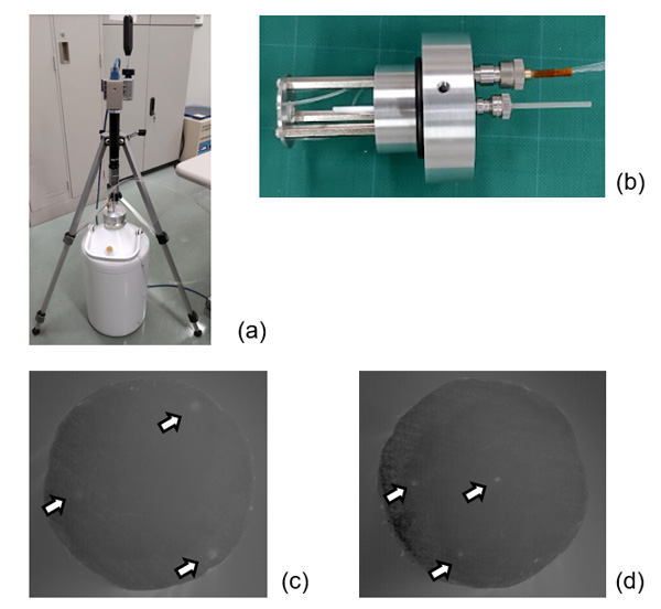
Figure 1 shows our preliminary test results using liquid nitrogen instead of liquid hydrogen. Figure 1 (a) shows the entire measurement setup. Figure 1 (b) shows the sensor head, wherein few of the three illuminating fibers, a lens, and the rigid fiber bundle for imaging are visible. Figures 1 (c) and (d) show images of reflected light spots appearing on the other end of the imaging fiber bundle. The distance between the sensor and the liquid surface is approximately 12 cm and 21 cm for Figs. 1 (c) and (d), respectively.
We thank Professor Teruo Bitoh for his assistance in developing the experimental setup. We also thank Professors Shin-ya Matsushita and Hiroto Kawashima for discussions and for providing us with liquid nitrogen, respectively. This research was supported in part by the grant donated by Eurus Energy Akita-Port Corporation to Akita Prefectural University.
FIG. 1. (a) All-optical non-contact liquid level sensor setup. (b) The sensor body. The pitch of the grid in the background is 50 mm. (c), (d): Images corresponding to two different liquid levels appearing on the end of the ϕ3.2 mm-diameter fiber bundle. See the main text for more information.
References
[1] Anne Sjoerd Brouwer, Machteld van den Broek, Ad Seebregts, and Andre Faaij, Impacts of large-scale Intermittent Renewable Energy Sources on electricity systems, and how these can be modeled, Renew. Sust. Energ. Rev. 33, 443-466 (2014).
[2] Mircea Ardelean and Philip Minnebo, HVDC Submarine Power Cables in the World, Joint Research Centre, European Union, Report EUR 27527 EN (2015).
[3] Paul Breeze, Hydrogen Energy Storage, Chapter 8, Power System Energy Storage Technologies, Pages 69-77, Academic Press (2018).
[4] Paul M. Grant, Chauncey Starr, and Thomas J. Overbye, A Power Grid for the Hydrogen Economy. Scientific American (June 2006).
[5] W. A. Olsen, A Survey of Mass and Level Gauging Techniques for Liquid Hydrogen. In: K.D. Timmerhaus (eds), Advances in Cryogenic Engineering, vol 8. Springer, Boston, MA. (1963).
[6] Koichi Matsumoto, Masamitsu Sobue, Kai Asamoto, Yuta Nishimura, Satoshi Abe, and Takenori Numazawa, Capacitive level sensor for liquid hydrogen, Cryogenics 51, 114-115 (2011).
[7] Ch. Haberstroh and G. Zick, A Superconductive MgB2 Level Sensor for Liquid Hydrogen, AIP Conference Proceedings 823, 679 (2006).
Keywords: Superconducting Power Transmission, Refrigerant Storage, Liquid Hydrogen, All-optical Non-contact Level Sensor