WB8-4
Orientation degrees in Dy123 powders by using Linear-drive type Modulated Rotating Magnetic Field system.
Dec. 1 14:25-14:40
*Walid Bin Ali1, Adachi Shintaro1, Fumiko Kimura1, Shigeru Horii1
Kyoto University of Advanced Science (Japan)1
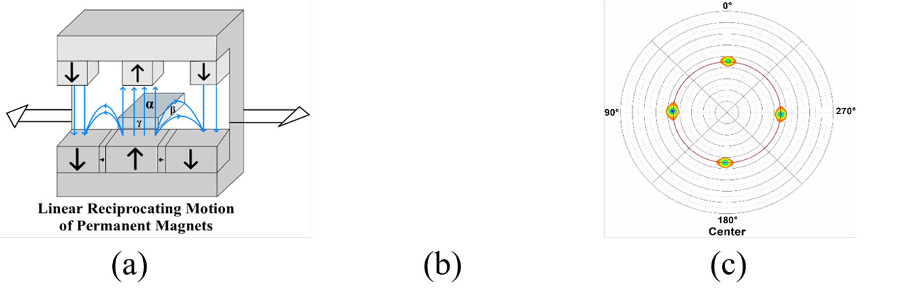
Due to their high critical temperatures (Tcs), rare-earth (RE) based cuprate superconductors are promising candidates for use in liquid-nitrogen-operated superconducting bulk magnets and cables. But their anisotropic crystal structures, which have alternating superconducting CuO2 layers and stacked layers of Cu-O chains, cause their critical current densities (Jcs) to be anisotropic within the crystal structure, Jc//c < Jc//ab. Furthermore, the inter-grain Jc is drastically reduced even for the c-axis oriented RE123 grains as the misorientation angle between them increases. For RE-based cuprate superconductors, tri-axial grain orientation is a serious issue for increasing the Jc. Thin film growth and melt-solidification processes based on epitaxial growth have been used in practice. Magnetic alignment is a bi-axial or tri-axial alignment process, and it is a non-vacuum process and can be done at ambient temperature. Permanent magnets can be a desirable choice for making the modulated rotating magnetic field (MRF) at a low cost and aligning HTSC in three-dimensional. Fig. (a) shows a schematic figure of a linear drive type modulated rotating magnetic field (MRF). The specimen with the sheet shape in Fig (a) is in the rest position, the permanent magnet array moves in a linear direction over the sample. Although introducing rotating magnetic fields into a linear production process is difficult, the present system that produces an MRF without moving the sample increases the adaptability of magnetic alignment as a material continuous production process. Initially, the sample was placed in the center of the array, α-plane was perpendicular to the linear motion of the unit. In principle, the first and second easy axis and the hard axis of magnetization are normally oriented to the α, β, and γ planes. This equipment employs a permanent magnet array composed of Nd-Fe-B to produce a static magnetic field (SF) and a rotating magnetic field (RF) up to 0.9T. Furthermore, fully oxidized Dy123 powder with a twin microstructure was aligned at ambient temperature in epoxy resin. To investigate the orientation degrees, the α-plane of the magnetically aligned samples of Dy123 was examined by an X-ray pole figure. Before explaining the pole figure results of the aligned sample of Dy123 under the MRF, I would like to explain the size of the sample. As aligned samples have dimension of 10mmD x 2.8mmW x 10mmH. To clarify the position-dependent orientation degrees, the aligned sample was cut into 3 different parts; the center part dimension is 4mmD x 2.8mmW x 4mmH, while the dimensions of the two different side parts are 3mmD x 2.8mmW x 10mmH in the direction of linear-reciprocating motion of the magnet. The XRD patterns of α, β, and γ of the magnetically aligned sample of Dy123 in epoxy resin under the linear-drive MRF were measured. Before cutting, the XRD pattern at the α-plane indicates that the first easy axis (c-axis) was aligned at ambient temperature. In the XRD patterns of the β and γ planes, the coexistence of the (h00) and (0k0) peaks appeared, which can be understood in terms of the presence of twin-microstructure in the ab-plane of Dy123. In the pole figure of the (103) plane, we observed four different diffraction spots in circumferential symmetry. Figure (b) shows the pole figure result for the magnetically aligned Dy123 sample before cutting. In detail, four-fold symmetric spots are located at 45 degrees. These four distinct diffraction spots are because of the bi-axially oriented twin microstructure. Due to the twin microstructure, the slightly broadened four peaks can be attributed to a loss in magnetic anisotropy. The average FWHM value of these four peaks was ~10 degrees. Figure (c) shows the (103) pole figure of the center part, four-fold symmetric spots are located at 45 degrees, but the four peaks were sharpened and the FWHM value was changed to ~8 degrees. It is strongly suggested that the magnetic flux of the magnetic array is not uniform over the sample. In the current study, we found that the improvement of the spatial distribution of the magnetic flux over the sample was required, for this 3-D simulation work might be useful for analysis of the spatial distribution between the lower and upper arrays as future issues to be overcome. The in-plane orientation degree depends on the position of the sample, which is why the center part shows less broad peaks. Moreover, the side parts of the samples show a more tilted in-plane orientation degree, which verifies the statement of location dependence. The X-ray (103) pole figure of the side parts will be shown in the presentation.
Keywords: Magnetic anisotropy, Triaxial Alignment, Superconductor